The built-in lock on my home’s sliding door broke recently. An opportunity for improvement!
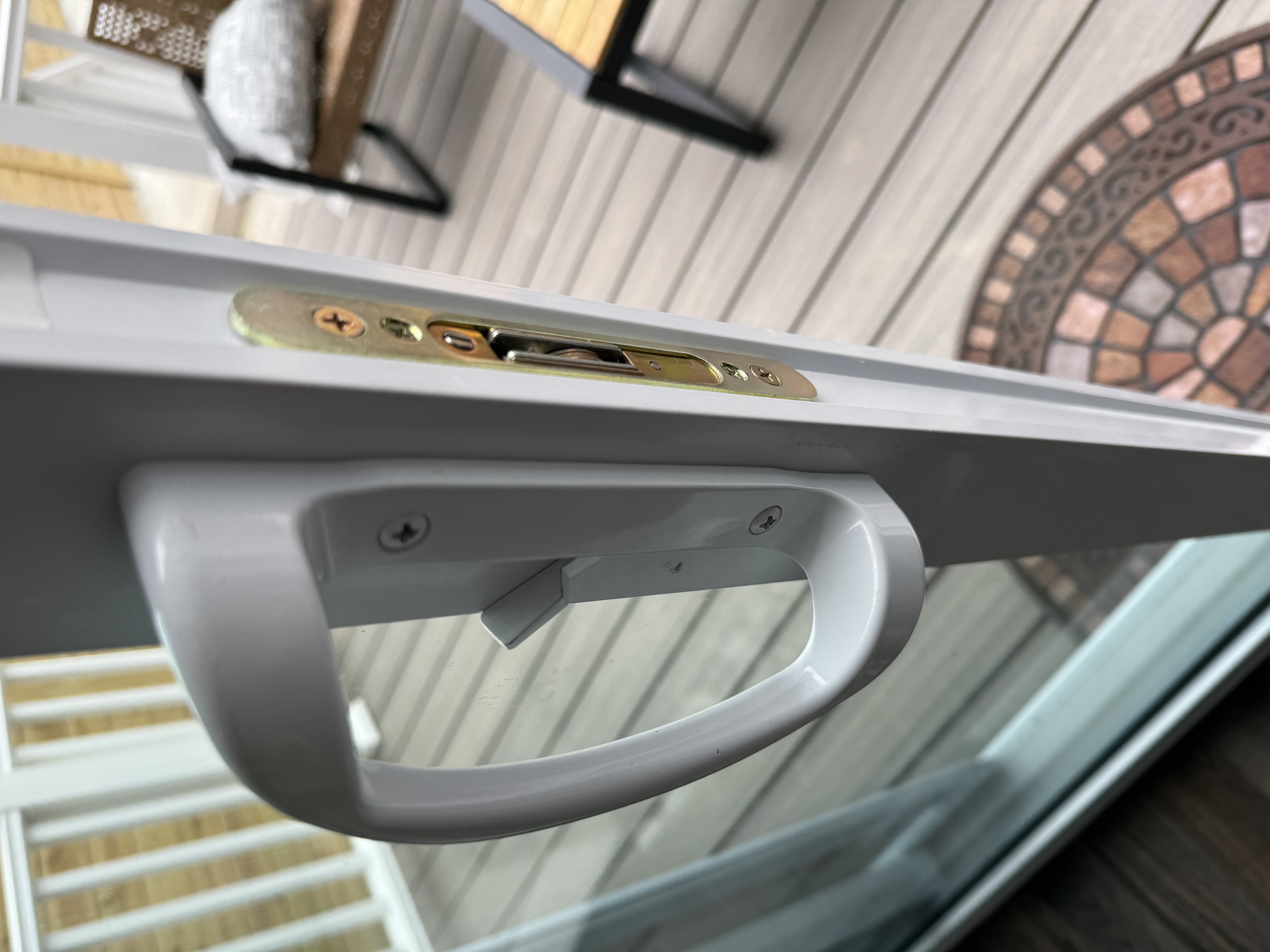
I have hated this lock since I moved in. There’s no key for it–it only locks from the inside. And I’ve never really trusted it would hold up to a good shove. Then it failed completely. As a placeholder, we’d been using a block of wood cut to the same size as the door to lay in the track.
Let’s build something better.
Here’s what I was looking for:
- Something sturdy to physically block the sliding door from moving.
- Lockable from outside. This would require automated movement.
- Phone-activated. My initial idea was to put an RFID tag on the outside of the house and be able to scan that from my phone to unlock. Only phones connected to our wifi would be able to activate the lock.
- From the inside, I didn’t want to have to use my phone to lock it. I wanted a simple physical button.
- Not too expensive. I didn’t buy any parts that cost more than $20.
The basic idea was to use a hobby servo’s movement to lift an arm in the track of the sliding door.
My first attempt used a continuous motion servo I already had on hand (from a previous project building a cat feeder). Unfortunately, it wasn’t nearly strong enough to lift the arm, plus the continuous motion type of servo wasn’t right for this project. I need to be able to control more precisely how far the arm was moving. I tried printing some gears to gain enough torque to make it work, but no dice.
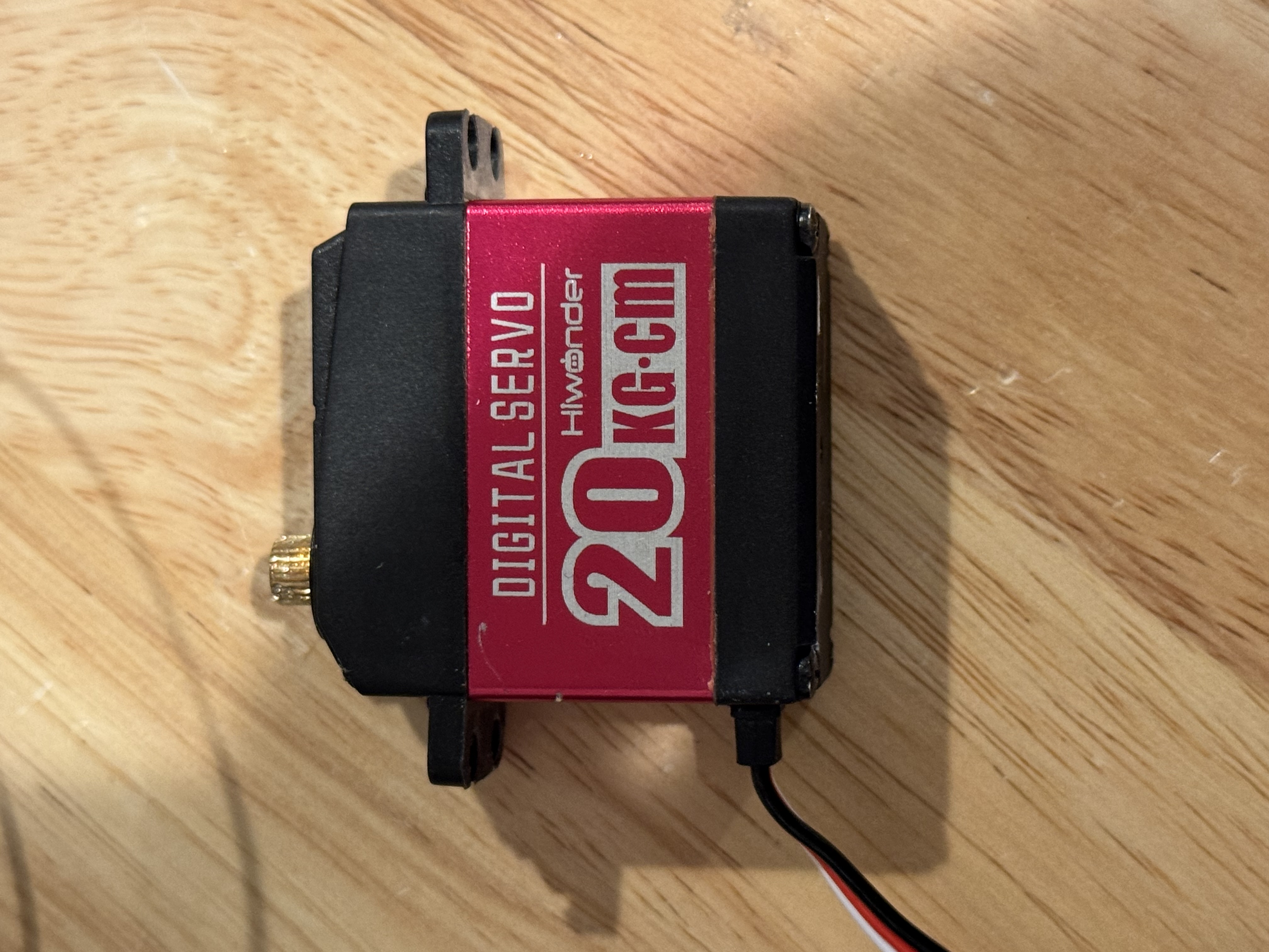
Next I picked up this bad boy. The 20 kg/cm of torque were enough to raise the arm, which I decided to 3D print instead of my initial idea of using a wooden broom handle. The plastic pole was a little lighter so the servo could lift it, but still sturdy enough.
Next I designed and 3D printed a box to hold the whole thing. After adding all the components (minus the arm) it looked like this:
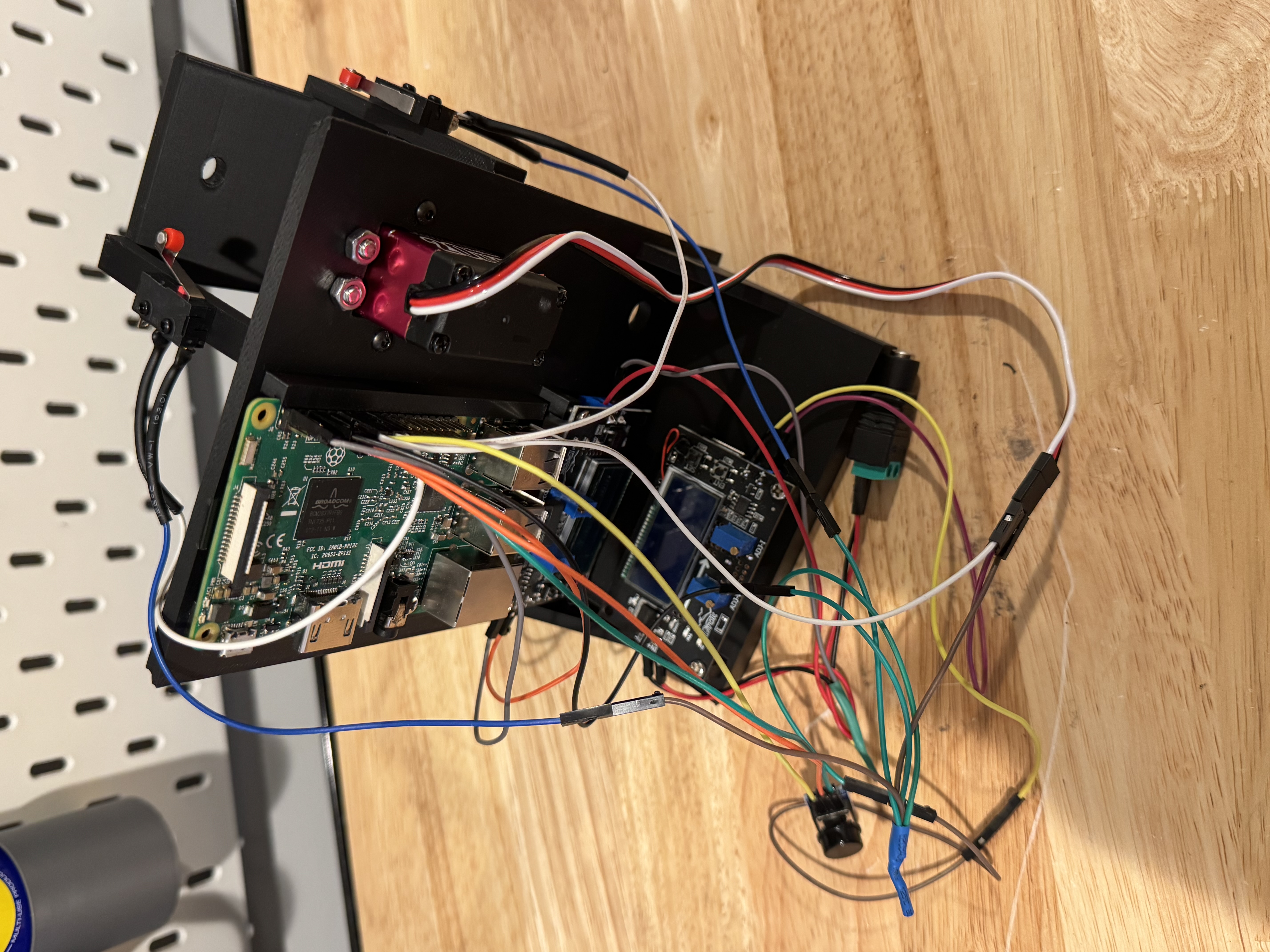
Beautiful, right?
Here’s what you’re looking at:
- Raspberry Pi (mine was a model 3B I had lying around).
- Two micro limit switches. I used these to detect when the arm has fully swept up or down.
- Two DROK DC buck converters. I used these along with a single 12V DC adapter to avoid having to plug in the servo and Pi separately. More about power supply in a moment.
- Hiwonder HPS 2018 positional servo. This has a range of 0-180 degrees, which was fine because I didn’t need any gears to raise the arm as the servo itself has sufficient torque.
- One momentary button. This is what I’ll use to activate the lock from inside the house so I don’t have to fumble for my phone to lock the door.
- Lots of wires.
When I started trying to use the HiWonder servo with the Raspberry Pi, I knew it would need its own power supply. I started by supplying it from a straight 6V line, but all I got was a faint clicking sound–a clear sign of undervoltage. The servo’s PDF spec sheet had the wrong voltage on it. It said it was 6-7.4V, but after a fair bit of testing I figured out it actually needed at least 8.2V to move at all. The website does have the right specification FWIW, but I didn’t realize that till later. Since I already had the buck converter to do that testing, I just bought a second one to make it easier to plug this whole project in at once.
Here’s the overall wiring diagram:
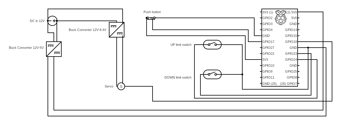
And here’s what the finished product looks like:
Want to try building this yourself? Here are the parts I used:
- Shaft coupler
- Buck Converter (x2)
- 6mm Steel Rod
- Hiwonder HPS 2018 Servo
- Limit switches
- Push button
- Assorted metric screws
- Different shaft coupler - this one is for the pole
- Wire
- Connectors
- Raspberry Pi (mine was a 3B that I had on hand)
- 12V power supply
- A few small screws to mount the buck converters and Raspberry Pi into place.
- A brick (explanation below)
Start by printing the main chassis and the side piece to hold the shaft and the pole. You’ll also need to print yourself a pole. I used this modular pole, but created a customized version that allows you to insert the second shaft coupler linked above. You can then secure that onto the 6mm shaft using two M3 screws.
You can print as many of the pole pieces as you need to match the size of your door, but you may need to print a modified one to get to the exact size needed. For me, it was a final piece on the end measuring 4 cm.
The servo mounts in the main chassis with M3 screws, and the side piece mounts on the main chassis with M2s. You can secure the limit switches on the side piece with M2 screws.
I tried to assemble the pole such that the radius of the shaft was about 10-15 cm from the left end of the pole, to reduce the torque required to lift the whole thing. Your mileage may vary depending on how wide your door is, but if you find the servo is shuddering/failing to lift, rebalancing might help.
Your Raspberry Pi will mount on the main chassis next to the servo, and there are places below it to mount your two buck converters. You’ll want to wire up the buck converters before mounting them. Everything else can be screwed into place and then wired up using the diagram above.
Once I had everything together, I found the whole thing was a little too top-heavy. To compensate, I decided the simplest solution was to print an extra space in the chassis for a good old American-style brick on the bottom. That did the trick nicely. If you have anything else of the same heft you can throw it in there instead.
You’ll need to print the cover and backside for the push button. You can slide the wires for the button through the hole in the cover, situate it in place, and then slide the backside on. I used a long length of wire to connect the three wires for the button and mount it at easy reach right by the door.
A few other parts to print:
I strongly recommend testing your buck converter’s output with a multimeter before connecting the power to your Raspberry Pi and servo. You can also insert a fuse into the wiring for extra protection.
Once it’s all connected, you can ssh into your Raspberry Pi or connect it to a screen and keyboard and do the following to set things up:
Update packages
sudo apt update
sudo apt upgrade -y
Install necessary packages
sudo apt install -y git python3 python3-venv python3-pip pigpio python3-pigpio
Ensure you have pigpiod
which pigpiod
Change to your home directory (or wherever you want to run the server from)
cd ~
Copy the source code
git clone https://github.com/riserperson/doorjam.git
Change to the project directory
cd doorjam
Create the venv
python3 -m venv venv
Activate and install Python dependencies
source venv/bin/activate
pip install --upgrade pip
pip install flask pigpio RPi.GPIO
deactivate
Open the sample config file and make any necessary changes (shouldn’t be needed as long as you have followed the same wiring I have.) Then change the name.
mv config-sample.py config.py
Start DoorJam and test
sudo pigpiod
cd ~/doorjam
source venv/bin/activate
python app.py
From another machine on the same network, you can test it by doing the following:
curl -H "X-API-Token: <YOUR_TOKEN>" http://<pi-ip>:8000/status
Or from a browser:
http://<pi-ip>:8000/
Stop the app with Ctrl+C
To make DoorJam run on boot:
sudo nano /etc/systemd/system/doorjam.service
Paste:
[Unit]
Description=DoorJam Lock Controller Server
After=network.target

[Service]
Type=simple
User=pi
WorkingDirectory=/home/pi/doorjam

# Run pigpiod as root before starting the app
PermissionsStartOnly=true
ExecStartPre=/usr/bin/pigpiod

# Run the app inside the venv
ExecStart=/home/pi/doorjam/venv/bin/python /home/pi/doorjam/app.py

Restart=always
RestartSec=3

[Install]
WantedBy=multi-user.target
Enable and start the service:
sudo systemctl daemon-reload
sudo systemctl enable doorjam.service
sudo systemctl restart doorjam.service
Check status
sudo systemctl status doorjam.service
Icing on the cake!
Once everything is setup and running, if you have an RFID sticker tag you can program your phone to open from the outside. Here’s how I did it on an iPhone:
- Create a new Shortcut and add the action “Get contents of URL”
- Enter the following for your url:
http://<pi-ip>:8000/toggle
NOTE that you may want to reserve an IP address for your Pi on your router’s configuration.
Under the details for the Action, include the following:
Method: POST

Headers: (add one)
Key: X-API-Token
Name: <your-token-from-config-file>
- Create a new Automation of the type “NFC”
Pair the automation with your NFC tag and then select your Shortcut that you created to run when it’s scanned.
That should do it! I put mine under weatherproof tape on the sliding door, and now I can unlock it anytime I want from outside.
Safety notes (important!)
- Do not power the servo from the Pi 5V rail.
- Use a dedicated buck converter for the servo supply and another for the Pi.
- Ensure all grounds are common (Pi GND and servo PSU GND must be tied together).
There are still a few ideas I have for further tweaks with this, like sending a signal via the push button to lock the door after a 30 second timer. But I’m very pleased with how this all came together from scratch.
If you try this on your own and have any other ideas for how to improve or get stuck while trying to put it all together, let me know! My coordinates for contact are below.